
Specifications
Computer Artificial Intelligence
The initial proposal for handling the artificial intelligence (AI) of the computer player to allow for a human vs. computer interaction consisted of the combined efforts of an alpha-beta-pruning search algorithm with a minimax algorithm. The basic premise of the minimax algorithm is a recursive evaluation method for choosing the next move for a player. In the scope of this project, the minimax algorithm is set for a two-player game: the human and the computer, with the human player being the maximizer and the computer being the minimizer respectively. This terminology is due to the fact that the human player is maximizing his chance to win while the computer player is minimizing that chance. In order for minimax to be carried out effectively, score values must be primed to each specific position of the board and must adapt to any given state/turn of the game. To better understand this, these score values merely indicate how beneficial it would be for a player to reach that position. Presented below is a schematic of this in a 4x4 playing board.
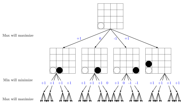
http://www.wieschoo.com/tutorials/optimization/connect4-ai-minimax/001189/
Without alpha-beta pruning, the minimax algorithm will simply evaluate all the score values across all the possible choices within its scope depth. By scope depth, we are referring to the number of moves that the algorithm will be looking ahead. Even if the lowest possible value for the minimizer has been found, without alpha-beta pruning, the algorithm will unnecessarily evaluate the other values as well, taking up processing power.
With the alpha-beta pruning search algorithm, the speed of minimaxing will be increased as once the lowest possible value has been discovered, the search is complete, effectively saving processing power and time.
Despite being a worthwhile solution to the programming associated with this project, no online documentation could be found for Connect4 Arduino. In the favor of saving project work time, the implementation of the alpha-beta pruning algorithm was dropped as unnecessary. This also opened up the door for taking example open source code found online for quick implementation and debugging. The code we were able to adapt was found at: http://www.swblabs.com/downloads/Connect4.pde
Scott. "Arduino Plays Connect4." SWB Labs. N.p., 12 Mar. 2012. Web. 1 Apr. 2014. <http://www.swblabs.com/?p=93>.
This code included a lot of neat things besides the necessary computer player algorithm such as sound files and serial print in’s that notify the human player about the state of the game. The sound files, due to their superfluous nature in this project, were removed but everything else was kept and modified to suit the needs of the project.
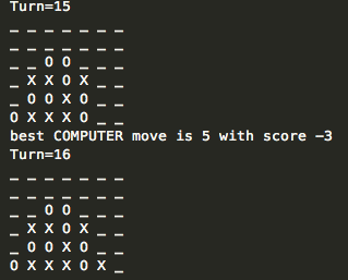
The greatest asset of utilizing this open source code was that it permitted debugging and refining way before the entire mechanical contraption of the hopper and board was fitted together. In this stage of testing, only the photo interrupt board needed to be linked up. Testing of the algorithm was done on the virtual board that was being printed into the Arduino environment serial monitor
With the alpha-beta pruning search algorithm, the speed of minimaxing will be increased as once the lowest possible value has been discovered, the search is complete, effectively saving processing power and time.
Despite being a worthwhile solution to the programming associated with this project, no online documentation could be found for Connect4 Arduino. In the favor of saving project work time, the implementation of the alpha-beta pruning algorithm was dropped as unnecessary. This also opened up the door for taking example open source code found online for quick implementation and debugging. The code we were able to adapt was found at: http://www.swblabs.com/downloads/Connect4.pde
Scott. "Arduino Plays Connect4." SWB Labs. N.p., 12 Mar. 2012. Web. 1 Apr. 2014. <http://www.swblabs.com/?p=93>.
This code included a lot of neat things besides the necessary computer player algorithm such as sound files and serial print in’s that notify the human player about the state of the game. The sound files, due to their superfluous nature in this project, were removed but everything else was kept and modified to suit the needs of the project.
The greatest asset of utilizing this open source code was that it permitted debugging and refining way before the entire mechanical contraption of the hopper and board was fitted together. In this stage of testing, only the photo interrupt board needed to be linked up. Testing of the algorithm was done on the virtual board that was being printed into the Arduino environment serial monitor

The flaw in utilizing this code was that the minimax algorithm was tied into just about every other piece in the code, so controlling scope depth posed a significant challenge. Even so, the AI algorithm was tested to provide the human player a fairly challenging opponent.
In terms of obstacles, the existence of circuitry problems in the custom printed circuit board proved to be the greatest set back in getting the AI up and running. These problems, which were made up of unusual short-circuiting and loose connections, most likely stemmed from the difficulty in soldering the individual photo interrupt sensors onto the board. The difficulty in this soldering job over another one is attributed to the extremely fine details of the printed board, where even an accidental drop of soldering material can and did compromise performance all together.
To solve this problem, a separate Arduino sketch outside of the AI was created to test the functionality of each photo interrupt sensor. The sensors operate with a default HIGH state when there is no interruption detected and switch to a LOW state otherwise. The calibration sketch simply initializes all the interrupts and allows for testing with each individual sensor. Should there be any problems at the circuit level, it can be traced and pinpointed easily.
Photo-Interrupt Board
The players actions are tracked using an array of photo interrupt sensors. The sensors consist of an Infrared Light emitting diode and a photo transistor, which changes voltage from high to low when the sensor is blocked. The sensors are connected through a costume milled printed circuit board that interfaces with the Arduino's digital I/O pins, shown below.

The milled printed circuit board was created by removing areas of copper from a sheet of printed circuit board material to create traces and pads, as shown below. The CNC mills a pattern according to a circuit board plan known as the layout file. The layout file created using a the program Eagle.

|

|
Positioning System
A rack and pinion is used to provide linear motion for the system. The pinion is driven by a DC motor mounted in the carriage while the rack is mounted to a stainless steel rail. The carriage is mounted to a Delrin slide that moves in a channel on the rail. A quadrature shaft encoder is mounted to the carriage with the drive shaft passing through it. The components for this system were purchased from Vex robotics as an off-the-shelf linear positioning system.

It is well known that Arduino is poorly suited for quadrature decoding because it does not update fast enough; it often misses counts. In order to have a reliable quadrature decoding system, a custom prototype board was made that used a LS7184 Quadrature Decoder IC with three cascaded CD416B Binary Counter ICs to handle the quadrature off the Due. The LS7184 takes in the signal from the shaft encoder and outputs a pulse and a direction. The binary counters take in the pulse and direction and maintain a binary absolute count of the position of the carriage. LEDs in the board show the current value of the count in binary. Because this system runs on 5V but the Due pins can only take a maximum of 3.3V, a voltage divider was used to step the 5V down to 3.3V. The Due interprets the binary output and drives the carriage appropriately. Two limit switches on the rail allow the carriage to calibrate itself.
The decoding was based on that described in the project report:
Anderson, Kristopher. "US Digital’s S2 Series Incremental Rotary Shaft Encoder and Interface." University of Florida Machine Intelligence Lab, 9 Dec. 2003. Web. 10 Feb. 2014. <http://tinyurl.com/quadReport>.
The decoding was based on that described in the project report:
Anderson, Kristopher. "US Digital’s S2 Series Incremental Rotary Shaft Encoder and Interface." University of Florida Machine Intelligence Lab, 9 Dec. 2003. Web. 10 Feb. 2014. <http://tinyurl.com/quadReport>.
| Quadrature Decoding Circuit Diagram |

Some problems were encountered with the tolerances of the gear components in the linear motion system; a large jump in the carriage was observed every time the pinion passed over a joint in the rack. The jump did not affect the measurement of the linear position, but it did cause a vibration in the hopper that was undesirable. After studying the issue, it was determined that the rack teeth were farther apart at the joint than throughout the rest of the rack. The extra space caused the teeth of the rack and of the pinion to conflict. Because there is some slack between the slide and the rail, the entire carriage shifted is order to accommodate the conflict. This problem was solved by filing down one of the teeth on the rack at each intersection.
Hopper

To enable our machine to deposit checkers, we created a custom hopper – made out of acrylic, ABS plastic, and aluminum – to hold them and dispense them. Our main feature is a spring-loaded mechanism to compress the tokens in a neat stack, which leads to consistent dispensing by a servo motor at the compressed end. In addition to the tubing that actually holds the checkers, there are four main components that make up the hopper: the plunger, cap, ramp, and attachment block.


The plunger was designed to have a head that has a slightly smaller diameter than the tube to keep the plunger pushing flush against the checkers and avoid jamming. The plunger rod is longer than the entire travel distance of the head, so it will act as a guide and the stopper at the end allows the user to pull the plunger back easily.


The plunger works in conjunction with the end cap, which screws into the end of the hopper, to compress our spring. The length of the cap is purposely three diameters of the plunger rod, a rule-of-thumb standard to ensure proper sliding. We made the cap threaded and screw onto the tube to allow the user to remove the cap and plunger and reload the hopper with relative ease.


On the other end of the hopper, we 3D printed the dispensing ramp using a FDM rapid prototyping machine. The ramp has a sleeve that fits over the tube, and a housing to hold the dispensing servo motor. We machined a semicircular arm fixture out of aluminum to extend the reach of the servo to reliably push the checkers into the opening.


Finally, we created an attachment block to fasten the hopper to the positioning setup. The attachment consists of two parts, a base and top. The top part of the attachment had a half-cylindrical pocket that the tube adhered to and the base was held to the positioning structure by screws. We machined it to attach using a dove-tail slide and tapered it slightly so it became rigid when it slid on all the way.
THE TEAM

TJ is a mechanical engineer who loves to program and debug automated Connect 4 games when he is not traveling the world. In addition to the crafty parts of this project, he assisted greatly in boosting morale and focus of the team. You can learn more about TJ here.

Mark.
Mark is also a 4th year mechanical engineering student focusing on solid mechanics. His specific responsibilities were machining and sensors. If he's not in class, you can usually find him in the machine shop or laboring away on an FEA code. During his weekends he enjoys cycling and participating in Berkeley's Formula SAE program. Upon graduation Mark will work in the energy industry. Learn more about Mark here.
Mark is also a 4th year mechanical engineering student focusing on solid mechanics. His specific responsibilities were machining and sensors. If he's not in class, you can usually find him in the machine shop or laboring away on an FEA code. During his weekends he enjoys cycling and participating in Berkeley's Formula SAE program. Upon graduation Mark will work in the energy industry. Learn more about Mark here.
Gordon is a 4th year mechanical engineering major with an interest in design. His responsibility in this project involved coding up the artificial intelligence of the computer player and debugging.
Louisa is a 4th year mechanical engineering major with an interest in mechanics of materials. She was responsible for the linear positioning of the carriage and assisted in the design of the hopper.

Zach is a 4th year mechanical engineering major whose interests are in product design, development and manufacturing. He was mainly responsible for the design of the hopper and worked with the team on the construction of the platform and structure of the machine.
Special Thanks to the Etcheverry Machine Shop Staff!
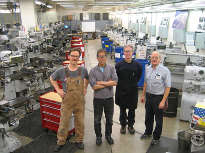
Gordon, Dennis, Scott, Mick, Jesse (not pictured) and Tom (not pictured)
